Recommended Ressource
As an introduction to reverse engineering, here is a list of good resources to help you understand basic concepts and get started:
- [Post FR] Lessons in Reversing (Beginner Level)
- [Doc EN] C Language (Beginner Level)
- [Post FR] C Language (Beginner Level)
- [Tool] Godbolt: See how a language’s code transforms to ASM
Reverse-Engineering : Key concept
Way of Reversing
There are two basic techniques for analyzing malware: static analysis and dynamic analysis.
Static analysis examines the executable without running it, using tools to inspect the decompiled instructions. We will focus on dynamic analysis, which involves using disassemblers and debuggers to analyze binaries while running them.
Popular tools include IDA, a multi-platform disassembler and debugger, and others like Ghidra and Binary Ninja. A disassembler converts an executable into Assembly Language instructions for debugging and manipulation.
let’s start with necessary knowledge
Binary Number System
Binary numbers are fundamental to computers. A bit is either on (1) or off (0). In binary, each column’s value is twice that of the column to its right, using only 0 and 1.
In decimal (base 10), the number 15 is calculated as (1 x 10) + (5 x 1) = 15. In binary (base 2), the same number is 1111.
We can compute it like this:

So, with 4 bits we can go to 0 to 15
with 4 more bits, we have 16+32+64+128 => we can go now to 0 to 255
Binary simplifies computer design by using only two digits, unlike the decimal system which uses ten digits (0-9).
Hexadecimal Number System
We learned that each number in binary represents a bit. Combining 8 bits gives us a byte, which can be divided into its top 4 bits and low 4 bits, called nibbles. Since 4 bits range from 0 to 15, a base 16 system (hexadecimal) is easier to work with.
Hexadecimal is used in x86 Assembly because it simplifies binary representation. Each column in hexadecimal has a value 16 times that of the column to its right. Besides 0-9, hexadecimal includes A-F, providing 16 different symbols.
Here is an example on how to convert easily:
Decimal : 255
255 ÷ 16  →  Quotient = 15,  Remainder = 15 (F)
15 ÷ 16  →  Quotient = 0,   Remainder = 15 (F)
So 255 = FF in hexadecimal
Value formating : Bytes, Words, …
Memory is measured in bytes. A byte is 8 bits. Two bytes form a word, four bytes form a double word (32-bit), and eight bytes form a quad word (64-bit).
A byte, being 2^8, has 256 possible values, ranging from 0 to 255.
For example , see the following C code :
int a;
short b;
unsigned char c;
Here int is integer : 4byte of data => 4*8bits = 32bits!
But there is a trap ! For an unsigned integer (32-bit), the range is from 0 to 2^32 - 1, which is 0 to 4,294,967,295.
For a signed integer (32-bit), the range is:
Positive range: From 0 to 2^31 - 1 (i.e., 0 to 2,147,483,647).
Negative range: From -2^31 to -1 (i.e., -2,147,483,648 to -1).
Thus, the total range for a 32-bit signed integer is from -2,147,483,648 to 2,147,483,647.
1 bit is used for sign.
Then Short is 2bytes : 16bits of signed data
And for finish : unsigned char is 1byte of unsigned data => 0 to 255
Integer overflow are a common source of vulnerability !
For example, play around with this Python code and see what value will overflow a type and bypass the check!
import ctypes

def add_tax_and_buy_house(user_input):
    tax = 10000
    price_final = ctypes.c_uint32(user_input + tax).value

    print(f"You buyed house with {price_final}$")
    if price_final >= 10000:
        print(f"So much money spent on this house...")
    else:
        print("how did you trick me")

user_input = int(input("Enter your price to buy a house: "))
add_tax_and_buy_house(user_input)
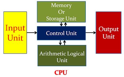
x86 Basic Architecture
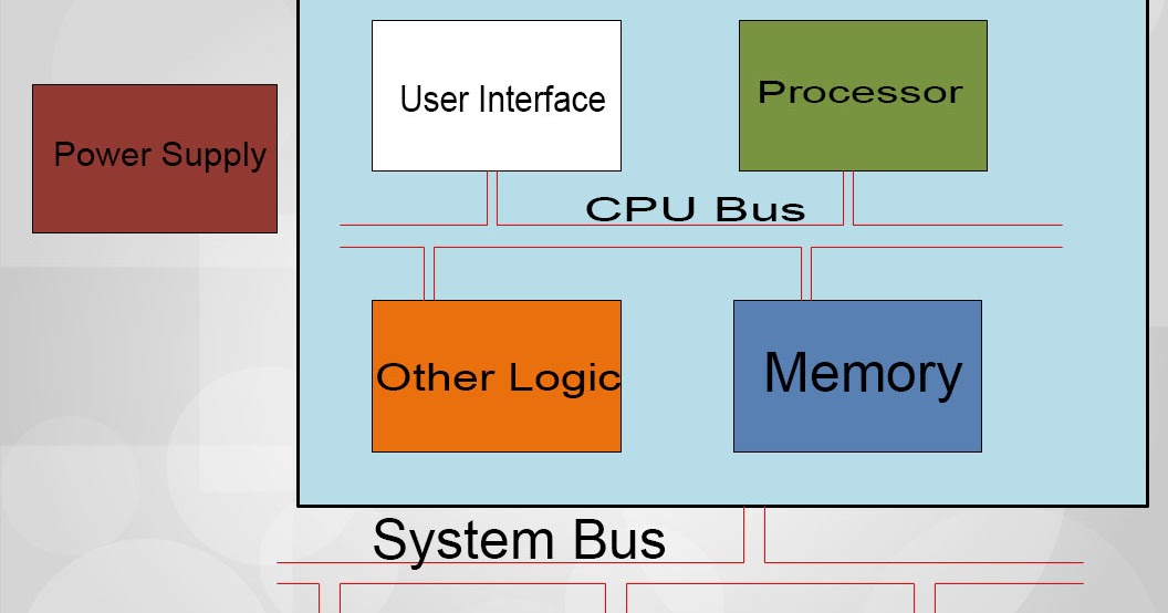
The CPU consists of four main composants:
- Control Unit: Retrieves, decodes, and manages instructions from memory.
- Execution Unit: Executes instructions and performs calculations.
- Registers: Temporary storage for data within the CPU.
- Flags: Indicate events during execution.
Common Registers
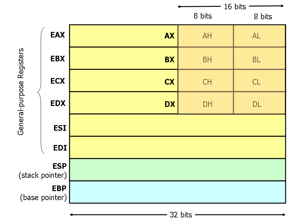
The general-purpose registers temporarily store data during processing. We’ll focus on the 32-bit x86 architecture.
Each new version of these registers is backward compatible. Let’s review the 8 general-purpose registers in IA-32 architecture:
EAX: Main register for arithmetic calculations, also known as the accumulator.EBX: Base Register, points to data in theDSsegment.ECX: Counter register, used for loops and string operations.EDX: General-purpose register, extendsEAXto 64-bits, used for I/O operations.ESI: Source Index, points to data in theDSsegment, used in string and array operations.EDI: Destination Index, points to data in theESsegment, used in string and array operations.EBP: Base Pointer, points to data on the stack (SSsegment), references local variables.ESP: Stack Pointer, points to the top of the stack frame, references local variables.
Each register is 32-bit (4 bytes). The lower 2 bytes of EAX, EBX, ECX, and EDX can be referenced by AX, and subdivided into AH (high byte) and AL (low byte). ESI, EDI, EBP, and ESP can be referenced by their 16-bit equivalents: SI, DI, BP, SP.
Segment Registers
Segment Registers
Segment registers reference memory locations. We’ll focus on the flat memory model.
There are six segment registers:
CS: Code segment, stores the base location of the code section (.text).DS: Data segment, stores the default location for variables (.data).ES: Extra segment, used during string operations.SS: Stack segment, stores the base location of the stack.FS: Extra segment.GS: Extra segment.
Each segment register is 16-bit and points to the start of a memory segment. The CS register points to the code segment, where instruction codes are stored. The processor retrieves instructions based on the CS value and an offset in the EIP register. Programs cannot explicitly change the CS register; the processor assigns its values.
The DS, ES, FS, and GS registers point to data segments, helping to separate data elements and prevent overlap. The SS register points to the stack segment, which contains data values passed to functions and procedures.
Instruction Pointer Register
The EIP (Extended Instruction Pointer) register in x86 architecture holds the address of the next instruction to be executed. It is a crucial component of the CPU’s control flow, ensuring that instructions are processed in the correct sequence. The EIP register is automatically updated after each instruction fetch, pointing to the subsequent instruction. Direct manipulation of EIP is not possible through regular instructions; instead, it is modified by control flow instructions such as jumps (jmp), calls (call), and returns (ret). This register is essential for the execution of programs, as it dictates the flow of execution within the code segment.
For example, this nop loop :
section .text
global _start

; assuming _start is at adress : 0x40000
_start:
    ; Simple instructions
    nop ; EIP¨= 0x40000 (nop is a 1byte instruction)
    jmp _start ; EIP = 0x40001 => jump to 0x40000
Control Registers
Control registers determine the CPU’s operating mode and task characteristics. There are five control registers:
CR0: Controls the operating mode and processor states.CR1: (Not Implemented)CR2: Holds memory page fault information.CR3: Contains memory page directory information.CR4: Flags for processor features and capabilities.
Values in control registers can’t be directly accessed. Instead, data can be moved to a general-purpose (GP) register for examination or modification. Kernel programmers typically modify control registers, while userland programs may query them to determine processor capabilities.
Flags
Flags are crucial in assembly language and program flow control, helping to verify and control program execution. The EFLAGS register in 32-bit assembly contains 32 bits of status, control, and system flags.
Status Flags
CF: Carry Flag - Set on unsigned integer overflow.PF: Parity Flag - Set if the number of 1 bits is even.AF: Adjust Flag - Set on carry/borrow from bit 3.ZF: Zero Flag - Set if the result is zero.SF: Sign Flag - Set to the sign bit of the result.OF: Overflow Flag - Set on signed integer overflow.
Control Flags
DF: Direction Flag - Controls string operation direction.
System Flags
TF: Trap Flag - Enables single-step mode for debugging.IF: Interrupt Enable Flag - Controls response to external signals.IOPL: I/O Privilege Level Flag - Defines access levels for I/O address space.NT: Nested Task Flag - Links current task to the previous one.RF: Resume Flag - Controls response to exceptions in debugging.VM: Virtual-8086 Mode Flag - Indicates virtual-8086 mode.AC: Alignment Check Flag - Enables alignment checking.VIF: Virtual Interrupt Flag - ReplicatesIFin virtual mode.VIP: Virtual Interrupt Pending Flag - Indicates pending interrupt in virtual mode.ID: Identification Flag - Indicates support forCPUIDinstruction.
Flags ensure each operation’s success and are essential for debugging and control in assembly language.
Here’s an example of how the cmp instruction works in assembly, showing which flag is set and how the jz (jump if zero) instruction uses the flag to branch to another part of the code:
section .text
    global _start

_start:
    mov eax, 5      ; Load 5 into eax
    mov ebx, 5      ; Load 5 into ebx
    cmp eax, ebx    ; Compare eax and ebx => they are the same so ZF is set to 1
    jz values_equal ; Jump to values_equal if zero flag (ZF) is set
    nop ; else, execute this if ZF is not set

value_equal:
    nop
In this example:
- The
cmpinstruction compares the values ineaxandebx. - If the values are equal, the zero flag (ZF) is set.
- The
jzinstruction checks the zero flag and jumps to thevalues_equallabel if the flag is set. - If the values are not equal, the code continues and execute next instruction :
nop
Stack
The stack grows downward from higher to lower memory addresses. The stack bottom is the highest valid address, and the stack limit is the lowest valid address. If the stack pointer goes below this, a stack overflow occurs, potentially allowing an attacker to take control. Modern OS protections help prevent this.
The stack operations are push and pop. Push sets the stack pointer to a smaller value and copies registers to the stack. Pop copies data from the stack to registers and adds to the stack pointer.
Each function call reserves a section of the stack called the stack frame, which contains:
- Return Address: The address to return to after the function completes.
- Saved Registers: Registers saved to preserve the calling function’s state.
- Local Variables: Variables declared within the function.
- Function Parameters: Arguments passed to the function.
- Stack Pointer (SP): Points to the top of the stack.
- Base Pointer (BP): Points to a fixed location within the stack frame for accessing parameters and variables.
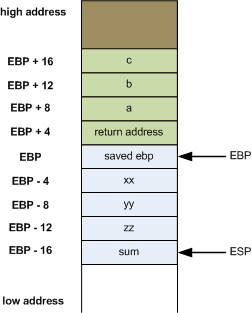
For example, this C code:
int foobar(int a, int b, int c)
{
    int xx = a + 2; // the compiler must push xx,yy,zz to stack as there are in locals variable
    int yy = b + 3;
    int zz = c + 4;
    int sum = xx + yy + zz;

    return xx * yy * zz + sum;
}

int main()
{
    return foobar(77, 88, 99); // push a,b,c args in stack (in x86, different in 64bits)
}
is represented in stack as :
Heap
The heap is a free-floating memory region managed by the CPU, larger than the stack. To allocate memory on the heap (userland, different on kernel side but same process), use malloc() or calloc(), and free it with free() to avoid memory leaks. Unlike the stack, the heap has no size restrictions and is accessible globally, making it ideal for large or dynamically-sized variables like arrays and structs. Heap memory is slower due to pointer access but necessary for variables that need to persist and be accessed globally.
For dynamic memory management, use malloc(), calloc(), realloc(), and free().
Some basic reversing examples
Simple C Program: Key Check
This simple C program demonstrates a basic key check within a function. The program defines a function check_key that takes an integer as an argument and compares it to a predefined key value 0x1234. If the key matches, the function returns 1 (true); otherwise, it returns 0 (false).
Here’s the code:
#include <stdio.h>

int check_key(int key) {
    if (key == 1234) {
        return 1; // Key matches
    } else {
        return 0; // Key does not match
    }
}

int main() {
    int user_key;
    printf("Enter the key: ");
    scanf("%d", &user_key);

    if (check_key(user_key)) {
        printf("Key is correct!\n");
    } else {
        printf("Key is incorrect.\n");
    }

    return 0;
}
we can compile it with GCC : gcc program.c -o program
Let’s see what’s happening in our favorite disassembler : IDA
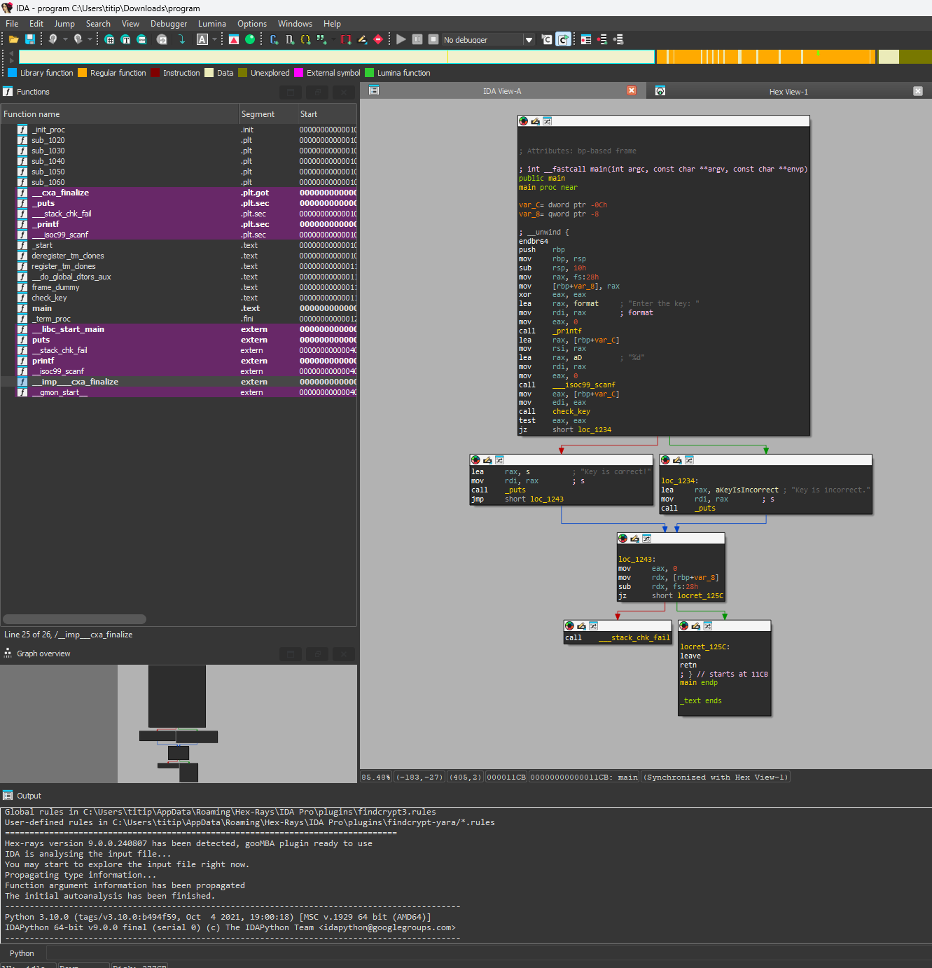
The IDA will display a basic view containing some usefull informations :
The IDA interface is divided into several key panels that provide essential information for reverse engineering:
- Disassembly View: Displays the assembly code of the binary, showing the instructions and their addresses.
- Hex View: Shows the raw hexadecimal representation of the binary data.
- Function Window: Lists all the functions identified in the binary, allowing quick navigation.
- Graph View: Visualizes the control flow of functions, making it easier to understand the program’s structure.
- Stack View: Displays the current state of the stack, useful for tracking function calls and local variables.
- Registers View: Shows the values of the CPU registers during debugging.
- Output Window: Logs messages and output from various IDA operations.
These panels provide a comprehensive overview of the binary, aiding in the reverse engineering process.
There is more pannels but we will use the basics pannel.
Now double left click on main in the Functions pannels. You can press Ctrl+F if mouse is inside function pannel to search a Function.
By default, you will have three modes of view:
- Graph view: Visualizes the control flow of functions.
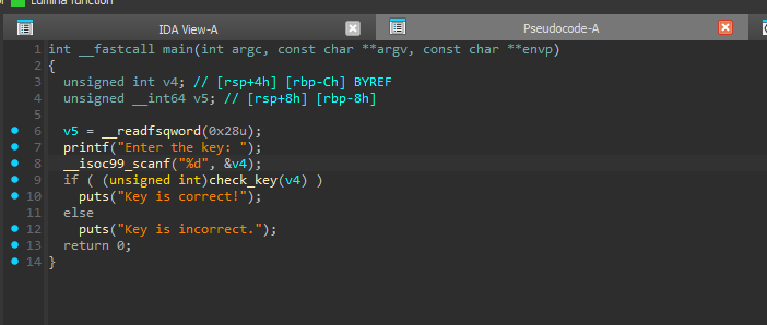
- Pseudo-code view: Shows decompiled source code based on heuristics.
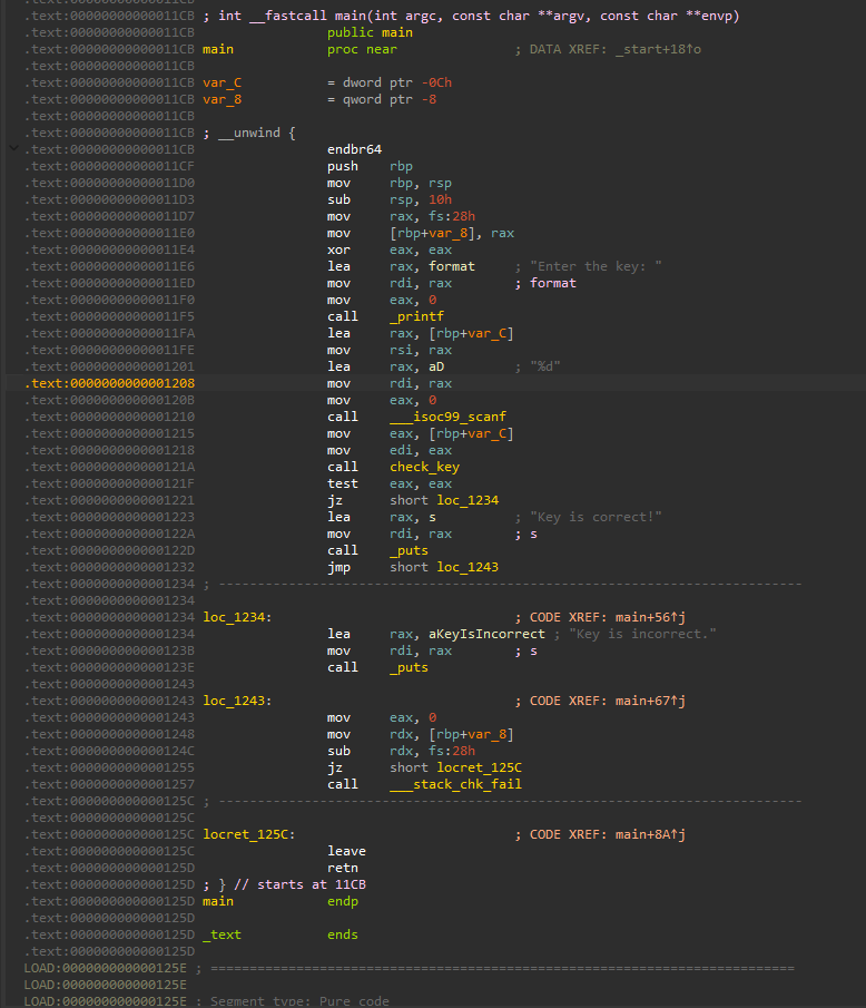
- Disassembler view: Displays raw disassembled instructions.
For example Pseudo-code (Decompiler) view :
and Disassembler View :
It’s tempting to rely solely on the decompiler and ignore the
ASMandGraphviews. However, beginners in reverse engineering should not neglect basicASMcomprehension. This is crucial, as relying only on the decompiler is like navigating a boat without knowing how to swim—if the boat crashes, you’re in trouble!
You can also press Tab when ASM View to switch to Decompiler view. Or space in ASM view to switch to Graph view. Or simply put view as you like in the general window of IDA. Customize as you want!
Additional information before going challenge
In the decompiler view, we see this:
v5 = __readfsqword(0x28);
This wasn’t in the original C code. Why is it there? In system security, concepts like canaries help secure programs. After long hours of coding in C, mistakes can happen, potentially leading to vulnerabilities.
The v5 = __readfsqword(0x28) refers to a canary, an 8-byte value stored in the stack. When a function ends, it checks the stored canary. If it differs, the program detects altered flow and crashes for safety.
This check isn’t shown in the decompiler but is visible in the Graph/ASM view (More reason to not entirely rely on decompiler !). At address 0x1248, the program checks the canary: it retrieves an 8-byte value from the stack, compares it to the stored value, and crashes if they differ.
There are many security concepts (Canary, ASLR, etc.), but we won’t analyze them now.
If you’ve read all of these, congratulations! Now that you are familiar with reversing, let’s start with some basic challenges to see what you’ve learned.
C01-01: A Basic Reversing Problem (Easy–)
Let’s begin with an introduction to reverse engineering.
The primary goal of this initial challenge is to gain a comprehensive understanding of various perspectives and basics within a basic disassembler. The flag is a password checker distributed across different locations, requiring you to explore a disassembler of your preference (such as IDA, Ghidra, BinaryNinja, etc.) to locate and piece together the complete flag.
For this challenge, the flag format is LRCTF{flag}.
You can validate with the password checker
C01-02: Encoding (Easy+)
After introduction1, I eliminated plaintext passwords stored in memory. Now, my flags will be safeguarded by a highly secure algorithm!
In this new exercise, you will delve into basic encodings and text manipulation within memory. The program has been stripped (no symbols for functions). Can you uncover the original library employed?
In reverse engineering, when encountering an end program value (transformed from start to end with a user password, for example), you will face two choices:
- Find a method to retrieve this value with the correct password by manipulating the data.
- Reverse the program from end to start: invert all algorithms, cryptographic functions, and so forth.
Which approach will you take?
You can validate with the password checker
Now that you’re familiar with basic C reversing, let’s see if you can understand more advanced C concepts!
C01-03: Shared Memory (Easy-)
Can you try to understand what this program is doing with the shared memory and internal structure?
A shared memory segment has been created at address 0x13000000. The program maps and executes the shellcode given in argv[1].
It is strongly recommended to complete the ASM x64 Exercises listed in the resources before attempting this challenge. The goal here is to learn how to write basic shellcode with NASM.
flag md5sum: b130cdd87480917a1b2a75ad4bc177c6
C01-04: IPC & Patching binary (Easy+)
In this challenge, an IPC is created and waits for a specific message. However, there is a random event that occurs after receiving your message…
Your goal here is to write a solver that sends the correct message and patches the original program to remove the unfortunate byte swap.
flag md5sum: f3985e9117865f5696182b17b973e822
C01-09 : Introduction to Crypto (Medium–)
Crypto is always important for reversing firmwares & binaries. In this first challenge of the series, you will need to identify the crypto algo behind this binary.
The flag format is LRCTF{PrintableAscii}.
flag md5sum: 9068e3550ef28714f79564c670db4cf8